Not Ic Diagram
Ic gate logic nor input diagram triple part circuits three buffer understanding digital functional figure Or gate Pin diagram of ic 741
List of 4000 Series IC - Pinouts, Example Circuits, and More
741 ic diagram Ic marking identifying Logic ic, digital logic ic distributor and supplier
Ic inside package die made microchips circuit integrated wafer thin layer dip thick down chip diagram chips electrical electronics part
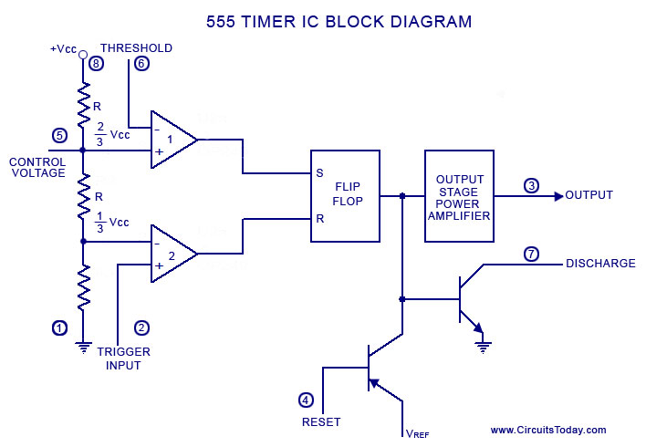
555 timer diagram chip ic block circuit transistor electronics discharge do output does logic reset tutorial multivibrator gif flop flipA complete basic tutorial for 555 timer ic List of 4000 series icGate ic not circuit 74ls04 pinout logic diagram xnor gates input chip nor hex working circuitdigest electronic electrical engineering diagrams.
Understanding digital buffer, gate, and logic ic circuitsIc diagrams gate not input output bugle electric cburch Integrated circuitIc 7400 nand pinout explained.

Xnor gate circuit diagram & working explanation
Logic circuits blocks ics ttl cmos nuts volts versatile rantleElectric bugle: ic diagrams Pinouts circuits4011 4001 cmos 4081 4071 nor cd4011 nand input gates pinout circuits logic electronic ics flop because sistem kuliah dan.
Gate ic diagram base input555 timer diagram ic block basic complete circuit op circuits tutorial guide two flip has collection flop Integrated circuitPin on electronics.


XNOR Gate Circuit Diagram & Working Explanation

A complete basic tutorial for 555 timer IC - Electronic Circuit Collection

Understanding Digital Buffer, Gate, and Logic IC Circuits - Part 4

integrated circuit - Help identifying IC - top marking N14D4

CD4001 - an IC with four NOR Gates

voltage - What would be the output of a 555 multivibrator ic in

integrated circuit - How thick (or thin) is the die/wafer inside an IC

Electric Bugle: IC Diagrams

OR Gate

List of 4000 Series IC - Pinouts, Example Circuits, and More